Category Archives: HOME

vSphere 6.0 : How SIOC works with Storage IO reservation

Storage IO control(aka SIOC) is one of the cool vSphere features since it got introduced in vSphere 4.1. As we know, whenever there is IO resource contention on shared storage, Storage IO control (SIOC) balances IOPS across the VMs based on the IOPS shares allocated to each VMDK on the VM. As IOPS distribution done by SIOC was only based on IOPS shares , in case of IO contention, there was not IOPS distribution guarantee for mission critical VMs. Also it was hard for admins to understand IO intensive worklaods and set the appropriate IOPS shares, in some cases even admin needs to re-calculate IOPS shares allocation based on workloads. Already there is increasing trend of moving tier-1 applications (which requires guaranteed performance) to vSphere. In order to take this trend of moving tier-1 applications on vSphere platform to the next level, it was very critical that SIOC also should consider storage IO reservation to satisfy service level agreements. I am really excited that VMware has added this feature as part of vSphere 6.0, with vSphere 6.0, SIOC is going to obey the storage IO reservation as well in terms of IOPS whenever there is IO contention. This is going to ensure the guaranteed performance in terms of IOPS. As part of vSphere beta program, I got chance to play with this feature & I would say this feature also going to ensure the greater level of IO performance isolation when admin puts more number of VMDKs per LUN. Now in addition to shares & limit, we have “reservation” as well to manage tier-1 IO(disk) intensive workloads using SIOC. It is important again to note that SIOC will only get invoked when there is IO contention ( based on set IO threshold in terms of latency)

In this post we will see couple of examples on how Storage IO reservation works with Storage IO control (SIOC).

Example 1:
Initial setup
-Say, We have 2 ESXi hosts (H1,H2) with 1 VM per host i.e. H1-VM1 & H2-VM2. Both host are attached to shared datastore DS1. i.e. Both VMs are on the datastore DS1( SIOC is enabled).

IOPS Shares/Reservation Configuration
-Initially each VM takes default share values i.e. Normal (say 1000). Hence VM1 & VM2 will have 1000 shares per VM.
-Consider max IOPS capacity of the shared datastore DS1 is 100 & we set IOPS reservation on VM1 as 60 and IOPS reservation on VM2 is NOT set.

How SIOC will behave
-In case IO contention, based on shares VM1 and VM2 will get 50 IOPS each as their shares are 1000 each but if we notice bit closer IOPS reservation set on the VM1 itself is 60, what happens now? When IOPS distribution based on shares per VM is less than the IO reservation set on the VM (this is our case), IOPS distributed to the VM will be based on IOPS reservation. Hence in our case, VM1 will get 60 IOPS and VM2 will get remaining IOPS i.e. 40.
– If reservation would not have there, each VM would have got IOPS in 1:1 ratio based on shares.

Example 2:
Initial setup is same as that of Example 1.

IOPS Shares/Reservation Configuration
– Share value set on VM1 is 500 & VM2 is 2000.
-Consider max IOPS capacity of the shared datastore DS1 is 100 & we set IOPS reservation on VM1 as 50 and IOPS reservation on VM2 is NOT set.

How SIOC will behave
-In case IO contention, based on shares VM1 will get IOPS distribution as 20 & and VM2 will get 80 but if we notice bit closer IOPS reservation set on the VM1 itself is 50, what happens now? When IOPS distribution based on shares per VM is less than the IO reservation set on the VM (this is our case), IOPS distributed to the VM will be based on IOPS reservation. Hence in our case, VM1 will get 50 IOPS and VM2 will get remaining IOPS i.e. 50.

My additional observations:
-When IOPS reservation set across VMs is more than the max IOPS capacity of the shared datastore, In case of IO contention, IOPS gets distributed in the ratio of set IOPS reservation.
-If IOPS calculation for particular VM based on share is more than the IOPS limit set on the same VM, that will IOPS upto limit set. SIOC will make sure IOPS distribution can not be more than the IOPS limit set on the VM.
-We can not set IOPS reservation more than the IOPS limit.

This is how, in case of IO contention, SIOC will make sure IOPS distribution across VM is guaranteed. I hope you enjoyed reading this post. Stay tuned for my next post on how to configure SIOC and storage IO reservation from vSphere API or web client.

In order to understand SIOC in detail, please refer SIOC detailed insight

PART 2: vSphere DPM vs ESXi memory ballooning

In PART I of my post we learned how vSphere DPM works & DPM memory demand metric. If you have not read PART I, I strongly recommend reading it first.

In PART 2 we will touch upon 2 important points with example.
1. How earlier vSphere DPM behavior was more aggressive from memory perspective?
2. How can we now control DPM behavior with new memory demand metric & avoid memory ballooning?

Let’s start with first point: How earlier DPM behavior was more aggressive?
OLD DPM memory demand metric was considering just Active memory as memory demand. To understand it clearly, we will take one example: Say we have 2 ESXi hosts(H1 & H2) with 2 VMs on each hosts(VM1,VM2 on H1 & VM3, VM4 on H2) in the DPM enabled cluster. Memory configuration was as follows:
H1-4GB
H2-4GB
VM1-3GB
VM2-3GB
VM3-3GB
VM4-3GB
Clearly environment is memory over-committed. All VMs are already powered ON, host consumed memory on H1 =3 GB, H2=1GB & current active memory usage on each VM is just 256MB. You may wonder that why host consumed memory is 3 GB on H1 when current active memory on H1 is just 512 MB(256x2VMs). The reason is, initially active memory usage for VMs on host H1 was 3GB but at this point active memory usage on H1 reduced to 512MB & as per the ESXi memory management, unused memory on the VMs will not freed itself to host until ESXi does not use its memory reclamation technique such as memory ballooning. Memory ballooning reclaims the VM memory only when host memory usage crosses 96% of its total host memory.

DPM will evaluate the cluster based on Target Resource Utilization Range = 63±18 i.e. Default range is 45 to 81%. As per active memory usage on both hosts, it is clear that only 1GB(256×4 VMs) memory is being used actively in the cluster which is just around 12.5% of the total memory (4 GB) available per host. Each ESXi host’s resource utilization demand is calculated as aggregate of memory required by VMs running on that host. Based on Target utilization range DPM identifies one of hosts as candidate host (in our case H2) to put into standby mode. DPM runs DRS simulation on the remaining one host i.e. H1 (DRS simulation will not consider the candidate hosts to be powered OFF, in our case it is H2), simulation uses the DPM demand metric formula i.e. just active memory to analyze whether VMs(VM3,VM4) on candidate host H2 can be accommodated on host H1 without impacting existing VMs(VM1,VM2). As the overall active memory across all the VMs is 1GB (256×4 VMs) & 1GB is just 25% of the memory utilization of H1 which is too less than upper target utilization range i.e. 81. (Before putting host into standby mode, DPM also makes sure that remaining host memory utilization should not cross the upper utilization range i.e. 81%). Hence DPM will vMotion VMs (with the help of DRS) from candidate host H2 to H1 and will put H2 into standby mode to save the power consumption. Note that by this time host consumed memory would be at-least 3 GB(earlier)+512 MB(VMs on H2 those are migrated to H1)=3.5 GB. If say, suddenly memory demand for recently migrated VMs increased by even 200MB each, host consumed memory on H1 would cross 96% of total memory available. This is where host H1 is very short on memory & it will immediately start memory ballooning in order to reclaim the unused VM memory to satisfy the memory demand by VMs. It is clear that old DPM memory demand metric did not consider future memory demand growth on any VMs those are currently on H1. Memory ballooning itself will not cause the performance impact as balloon driver will first reclaim the guest memory which is unused by guest OS which is perfectly safe (More on ballooning in next post). If memory is excessively over-committed & memory reclaimed by ballooning is not enough, it can lead to host swapping and it severally impacts the performance of the VMs.

Note: For the sake of simplicity in examples I did not consider memory required for virtualization layer.

Now you will be wondering, does not DPM evaluate(in above case) cluster to bring back the standby host H2 to meet the memory demand? Of course YES but as DPM evaluates hosts for power ON recommendation every 5 min, DPM will wait to complete the 5 min. As soon as DPM is invoked, DPM evaluates the cluster to bring back the standby host to meet the memory demand, once the standby host is powered ON, DRS balances the memory load in the cluster and it will stop the memory ballooning. However, hosts in the cluster may come across memory ballooning for the minimum time ranges from 5 min i.e. DPM invocation time for power on host recommendations + time DPM takes to evaluate the hosts + time required for the host to boot up from standby mode + Time required to vMotion as a result of balancing the memory load.

Overall, with DPM’s old memory demand metric DPM may lead to memory ballooning when active memory is low but host consumed memory is high. Host consumed memory can be high with low active memory when allocated VMs memory is either overcommitted OR it can even happen when VMs memory is fully backed by physical memory.

At this point I assume that you clearly understood that how earlier memory demand metric (active memory) was very aggressive.

Now it is time to see, how can we now control DPM behavior with new memory demand metric?
In order to control DPM’s aggressiveness, from vCenter 5.1 U2c onwards and all the versions of vCenter 5.5, DPM can be tuned to consider idle consumed memory as well in DPM memory demand metric. i.e. new DPM memory demand metric = active memory + X% of idle consumed memory. Default value of the X is 25. X value can be modified by using DRS advanced option “ PercentIdleMBInMemDemand” on cluster level. We can set this value in the range from 0 to 100. Refer this KB on how to configure PercentIdleMBInMemDemand advanced option.

We will continue the same above example:
We set “PercentIdleMBInMemDemand” option to 100 i.e. X value is 100. Initially on H1 host consumed memory was 3 GB & active memory usage was 512MB (256×2 VMs) and on H2 host consumed memory was 1 GB & active memory usage was 512MB(256×2 VMs). In this case when DPM evaluates the cluster, as host H2 has less than 45% memory usage, DPM picks host H2 as candidate host in order to put H2 into standby mode. DPM runs DRS simulation without considering the host H2 as it is a identified candidate host to be put into standby mode. DRS simulation uses DPM new demand memory metric i.e. Active memory + X% of idle consumed memory. Active memory on H1 is 512 MB, hence idle consumed memory on H1 is 3GB-512 MB=2.5GB. It shows that memory demand on H1 is 3 GB as X is 100. Active memory usage for the VMs on H2 those are going to be migrated to H1 (only if DPM finalizes to put H2 into standby mode) is 512 MBs, hence idle consumed memory on H2 is 1GB-512 MB=512 MB, it shows memory demand for VMs on H2 is 1 GB as X is 100. Finally, total memory demand by DPM is 4GB (3GB from VMs on H1 and 1 GB from VMs on H2), 4GB memory demand is way out of memory utilization target range i.e. 81%. As total memory demand by all the VMs goes out of utilization target range(Default range 45%-81%), DPM does not see any value in putting H2 into standby mode as for DPM performance is preference than saving power consumption, hence DPM will not put any host into standby mode & consequently avoids memory ballooning. This example shows that when there is high consumed memory and low active memory usage in your environment, it is better to set DRS advanced option PercentIdleMBInMemDemand to 100.

Note: DRS memory demand metric also uses the same formula but in this post I have just focused on DPM.

Now I am sure that you understood how DPM’s new memory demand metric can be used to fine tune DPM behavior which in turn can help to avoid memory ballooning.

is there direct relationship between new DPM memory demand metric and ESXi host memory ballooning. Answer is NO. There is NO direct relationship between new DPM memory demand metric and VM memory ballooning. New memory demand metric just gives us configurable option to fine tune DPM to consider more consumed memory as future memory demand while making host power ON/Off decisions. This would keep more memory resources available in cluster. Hence, it should indirectly avoid the ballooning.
It is also important to note that, DPM will not power on the standby host only because ballooning is happening on other host in the cluster as there is no direct relation between ballooning and DPM. In this case as well, when DPM gets invoked, it will check the target utilization range and only if host memory utilization exceeds the range, it starts evaluating the standby host based on memory demand formula (active memory + X% of idle consumed memory) in order to take hosts out of standby mode.
However, memory ballooning on VMs may happen (when host(s) are in standby mode) very rarely as DPM already would have considered conservative X% value before putting hosts into standby mode i.e. DPM would have kept enough memory resources(of course it is depend on the value of X i.e. PercentIdleMBInMemDemand) available in the cluster before putting any host into standby. Even then if ballooning happens, it is mean that there is excessive memory over commitment and/or actual memory demand by powered ON VMs is more than anticipated by DPM (using active + X% idle consumed).

Can actual memory demand of powered ON VMs be more than anticipated by DPM (which was based on new demand metric)? Yes, it can happen in very rare cases that too due to highly unpredictable increase in memory workloads/usage . Ex. Say cluster has 2 hosts(H1 and H2) with 1 VM on each. Consider, VM on a H1 has 8GB memory allocated but only 3GB is consumed by VM at the moment & X is set to 100. If X is 100, DPM considers entire consumed memory as memory demand. Based on 3GB memory demand, DPM puts host into standby mode (consider 3 GB is available on other host H2) but unfortunately, the moment DPM put the host into standby mode, memory demand of the VM got increased & consumed memory for the VM reached to say 7GB (very corner case) which is 4GB more than DPM had just anticipated. Now if host H2 does not have memory to satisfy this memory demand, it can lead to ballooning. However, once DPM realizes that memory utilization range is exceeding the target utilization range, it again evaluates cluster to bring back the standby host. It is worth to note that if VMs shares,limits & reservations are misconfigured, it can lead to ballooning even if there is plenty of memory available on host. (More on this in next post).

I hope you enjoyed DPM memory behavior, please leave the comment if you have any query. Stay tuned for PART 3 post on ESXi memory ballooning & memory best practices.

If you want to have even more depth understanding of DPM, please refer below resources
1. White Paper on DPM by VMware
2. Great book by “Duncan & Frank”: VMware vSphere 5.1 Clustering Deepdive

PART 1: vSphere DPM vs ESXi memory ballooning

One question is always getting popped into my inbox , the question is: can vSphere DPM lead to ESXi host memory ballooning? if yes, is there any way we can fine tune vSphere DPM to avoid the memory ballooning? I explained it whenever possible but when this question keeps popping up again and again, I thought its better to write one posts to give overview of the vSphere DPM, its memory demand metric and how memory ballooning relates to DPM.

I have divided this post in 3 parts as follows
Part 1: DPM basic overview & its memory demand metric calculations.
Part 2 : DPM vs Memory ballooning & memory best practices.
Part 3: What are the ways we can fine tune DPM?

Today I have covered Part 1 : “DPM basic overview & its memory demand metric calculations”.

DPM basic overview:
As we already know that consolidation of physical servers into virtual machines reduces significant power consumption. VMware DPM (Distributed Power Management) takes this reduction in power consumption to the next level.
DPM is feature of VMware DRS (Distributed Resource Scheduler), once we enable DRS on cluster from vSphere client or Web client, enabling DPM is just a click away. DRS does dynamic CPU and memory load balancing across all ESXi in the cluster & DPM does the evaluation of each ESXi host in the cluster so that DPM can put one or more hosts into standby mode (Power OFF) to save the power consumption OR bring back one or more hosts from standby mode to meet the resource (cpu, memory) demand of virtual machines in the cluster. You might be wondering how DPM evaluates ESXi host? It is the Target Resource utilization Range that plays the crucial role. DPM calculates Target Resource Utilization Range as follows.

Target Resource Utilization Range = DemandCapacityRatioTarget ±
DemandCapacityRatioToleranceHost

DemandCapacityRatioTarget is the target utilization of the ESXi host in the cluster. By default this is set at 63%.
DemandCapacityRatioToleranceHost sets the tolerance value around target utilization of each ESXi host, by default this is set at 18%.
Hence, by default, Target Resource Utilization Range = 63±18 i.e. Range is 45 to 81%

It is mean that DPM try its best to keep the ESXi host resource utilization in the range between 45 and 81 percent. If resource utilization of cpu or memory on each ESXi host is below 45%, DPM evaluates that host for putting into standby mode (Power OFF). If the resource utilization exceeds the 81% of either CPU or memory resources, DPM evaluates ESXi host to bring back that hosts from standby mode.
Note: DPM considers CPU & memory as resource for evaluation however, In this blog post, we would be focusing only on memory resource.

Basic terms:
Active memory: Memory which is being actively used at any point of moment by VM. This keeps changing as the VM load increases or decreases.

Consumed memory: It is the memory consumed by VM since it is booted. Note that consumed memory is not the same as memory allocated to VM. Consumed memory can be equal to allocated (configured) memory if & only if VM consumes entire memory allocated to VM. ESXi host never allocates memory to any VM until that VM touches/requests the host memory. When VM is powered off consumed memory would be zero. It is good to note that every VM only can get min(Configured memory, specified limit). When VM is powered OFF, consumed memory would be zero. If there is no any limit set on VM, configured memory itself will be default limit.

DPM memory demand metric.

In earlier releases, DPM was just considering active memory as memory demand from each VM on the host. i.e. “DPM memory demand metric=active memory” which is aggressive. In order to control DPM’s aggressiveness, with version vCenter 5.1 U2c onwards and all the versions of vCenter 5.5, DPM can be tuned to consider idle consumed memory as well in DPM memory demand metric. i.e. DPM memory demand metric = active memory + X% of idle consumed memory.

1. Default value of the X is 25. X value can be modified by using DRS advanced option “ PercentIdleMBInMemDemand” on cluster level. We can set this value in the range from 0 to 100. When we set this value to 0, it is mean that DPM will be aggressive the way it was in earlier release & as we increase X value DPM keeps becoming less aggressive. If X value is 100, it is mean that DPM considers entire consumed memory as memory demand. (Consumed memory =active memory + idle consumed memory).

2. Example. : Say, we have one VM with 8192MB (8GB) configured memory. Consider since the VM is booted, VM has consumed 6144MB (6GB) memory from host but only 20% is being used actively, hence active memory would be 20% of 6144 MB=1228.8 MB. Idle consumed memory =6144-1228.8=4915.2 MB. If X value is 25 then DPM memory demand would be=1228.8 + 25 % of 4915.2 =2457.6 MB + overhead. Setting X to 25 means, DPM considers 25% of idle consume memory as a demand by VM to avoid performance impact. As we increase X, DPM becomes more conservative. Hence user needs to set the X value as per his environment & requirement.

3. DPM Power OFF recommendations: Based on Target Resource utilization range, DPM evaluates candidate hosts to put into standby mode (i.e. When utilization is under 45%), and then DPM takes help from DRS to run the simulations considering candidate hosts are powered off in the cluster. These DRS simulations internally use the DPM memory demand metric (active memory + X% of idle consumed memory) to calculate the memory demand by each VM in the cluster. These simulations will be used by DPM to see if there is improvement in Target Resource Utilization Range when candidate host(s) is powered OFF. If resource utilization of the all non-candidate hosts is within the target range (i.e. 45%-81%), DPM puts the candidate hosts into standby mode & saves the power.

4. DPM Power ON recommendations: DPM evaluates each standby host when resource utilization of the powered ON host is above 81%, and then DPM takes help from DRS to run the simulations considering standby host(s) is powered ON in the cluster. These DRS simulations internally use the DPM memory demand metric (active memory + X% of idle consumed memory) to calculate the memory demand by each VM in the cluster & distributes the VMs across all hosts. These simulations will be used by DPM to see if there is improvement in Target Resource Utilization Range when standby host(s) is powered-on. If resource utilization of the all hosts is within the target range, DPM generates host power ON recommendations.

I hope you enjoyed how DPM works in general, please do leave comment for any clarification & stay tuned for exciting PART 2 “DPM vs Memory ballooning & memory best practices.”

If you want to have even more depth understanding of DPM, please refer below resources
1. White Paper on DPM by VMware
2. Great book by “Duncan & Frank”: VMware vSphere 5.1 Clustering Deepdive

DRS rules PART II: How to create VM-VM affinity rules using vSphere API.

In my last post we learned how to create VM-Host DRS affinity rules using vSphere API. Now today in PART II, we will see how to create VM-VM affinity rules using vSphere API. Before jumping on API coding, I would like to list out what VM-VM affinity rules are there and when we should use these rules.

What are the DRS VM-VM rules we can create on ESXi host cluster.

1. VM-VM affinity rule: This rule will keep the 1 or more VMs together on a host. i.e. DRS will make sure these VMs are running together on the same host all the time. Note that, this rule is soft rule, it is mean that, DRS can violate this rule if required in order to balance the cpu/memory load on the cluster. However, DRS will try its best to resolve this rule violation in next DRS invocation(Default DRS invocation is 5 mins).

Use cases:
1. If there is a group of VMs in DRS cluster those communicate frequently with each other, it would make sense to keep these VMs together on the same host to save some network bandwidth & increase the performance. If we keep such VMs on separate hosts, network traffic should exit from external physical network & will impact network latency.
2. If there is group of VMs in DRS cluster with same GuestOS, Apps or user data, we can keep these VMs together on same host to take advantage of Transparent Page Sharing (TPS) memory reclamation technique, so that host memory will be efficiently shared wherever there is opportunity.
Both of above use-cases can be satisfied by using VM-VM affinity rule

2. VM-VM anti-affinity rule: This rule is exactly opposite to above rule. Here this rule will keep 2 or more VMs away from each other. As per this rule, all the VMs involved in this rule should run on separate hosts. Again this rule is soft rule and DRS can violate this rule if required.
Use case:
If you want to make 2 critical VMs highly available, it makes sense to configure VM-VM anti-affinity rule on these 2 critical VMs. If one host goes down, second VM will be still running.

I strongly suggest you to read my blog post is HA aware of DRS rules in order to understand impact of above DRS rules on vSphere HA.

Note: All DRS rules are very popular among VMware admin but it is important to note that, if there are multiple rules configured on DRS cluster, it can impose constraint on DRS load balancing ability as DRS has to think on satisfying configured rules on cluster. It reduces DRS migration options. Hence please make use of these rules if absolutely required.

Creating these rules using vSphere API
Now with above basic fundamentals on DRS rules, we are ready to deal with creating these rules using vSphere APIs. I assume now you are familiar with vSphere API reference, go through below pointed data-object in detail so that you will understand code yourself. (Click on image to enlarge)
VMVMrules Dataobject
Refer: ClusterRuleInfo data object API reference

Below program creates both VM-VM affinity rule and VM-VM anti-affinity rule
[java]
package com.vmware.vijava;
import java.net.MalformedURLException;
import java.net.URL;
import java.rmi.RemoteException;
import com.vmware.vim25.ArrayUpdateOperation;
import com.vmware.vim25.ClusterAffinityRuleSpec;
import com.vmware.vim25.ClusterAntiAffinityRuleSpec;
import com.vmware.vim25.ClusterConfigSpec;
import com.vmware.vim25.ClusterRuleSpec;
import com.vmware.vim25.InvalidProperty;
import com.vmware.vim25.ManagedObjectReference;
import com.vmware.vim25.RuntimeFault;
import com.vmware.vim25.mo.ClusterComputeResource;
import com.vmware.vim25.mo.Folder;
import com.vmware.vim25.mo.InventoryNavigator;
import com.vmware.vim25.mo.ServiceInstance;
import com.vmware.vim25.mo.VirtualMachine;
import com.vmware.vim25.mo.util.MorUtil;

public class DRSVMVMRules {

public static void main(String[] args) throws InvalidProperty,
RuntimeFault, RemoteException, MalformedURLException {
ServiceInstance si = new ServiceInstance(new URL(args[0]), args[1],
args[2], true); // Pass 3 argument as vCenterIP/username/password
String ClusterName = "BLR-NTP"; // Cluster Name
String affineVM1 = "CentOS6_x64_2GB_1"; // First VM for affinity rule
String affineVM2 = "CentOS6_x64_2GB_2"; // Second VM for affinity rule
String anti_affineVM1 = "CentOS6_x64_2GB_3"; // First VM for anti-affinity rule
String anti_affineVM2 = "CentOS6_x64_2GB_4"; // Second VM for anti-affinity rule
Folder rootFolder = si.getRootFolder();

ClusterComputeResource cluster = null;
cluster = (ClusterComputeResource) new InventoryNavigator(rootFolder)
.searchManagedEntity("ClusterComputeResource", ClusterName);
ManagedObjectReference ClusterMor = cluster.getMOR();
ClusterComputeResource ccr = (ClusterComputeResource) MorUtil
.createExactManagedEntity(si.getServerConnection(), ClusterMor);

// VM-VM affinity rule configuration
ClusterConfigSpec ccs = new ClusterConfigSpec();
ClusterAffinityRuleSpec cars = null;
VirtualMachine vm1 = (VirtualMachine) new InventoryNavigator(rootFolder)
.searchManagedEntity("VirtualMachine", affineVM1);
VirtualMachine vm2 = (VirtualMachine) new InventoryNavigator(rootFolder)
.searchManagedEntity("VirtualMachine", affineVM2);
ManagedObjectReference vmMor1 = vm1.getMOR();
ManagedObjectReference vmMor2 = vm2.getMOR();
ManagedObjectReference[] vmMors1 = new ManagedObjectReference[] {
vmMor1, vmMor2 };
cars = new ClusterAffinityRuleSpec();
cars.setName("VM-VM Affinity Rule");
cars.setEnabled(true);
cars.setVm(vmMors1);
ClusterRuleSpec crs1 = new ClusterRuleSpec();
crs1.setOperation(ArrayUpdateOperation.add);
crs1.setInfo(cars);

// VM-VM Anti-affinity rule configuration
ClusterAntiAffinityRuleSpec caars = null;
VirtualMachine vm3 = (VirtualMachine) new InventoryNavigator(rootFolder)
.searchManagedEntity("VirtualMachine", anti_affineVM1);
VirtualMachine vm4 = (VirtualMachine) new InventoryNavigator(rootFolder)
.searchManagedEntity("VirtualMachine", anti_affineVM2);
ManagedObjectReference vmMor3 = vm3.getMOR();
ManagedObjectReference vmMor4 = vm4.getMOR();
ManagedObjectReference[] vmMors2 = new ManagedObjectReference[] {
vmMor3, vmMor4 };
caars = new ClusterAntiAffinityRuleSpec();
caars.setName("VM-VM Anti-Affinity Rule");
caars.setEnabled(true);
caars.setVm(vmMors2);
ClusterRuleSpec crs2 = new ClusterRuleSpec();
crs2.setOperation(ArrayUpdateOperation.add);
crs2.setInfo(caars);

// Passing the rule spec
ccs.setRulesSpec(new ClusterRuleSpec[] { crs1, crs2 });
// Reconfigure the cluster
ccr.reconfigureCluster_Task(ccs, true);
System.out.println("Rules are created with no issues:");

}
}
[/java]

Code itself is self explanatory, just map the code with data-objects in vSphere API reference. Note that for the sake of simplicity, I have hard-coded VM/Cluster name , do make changes according to your environment. Please do leave the comment if you have any doubt.

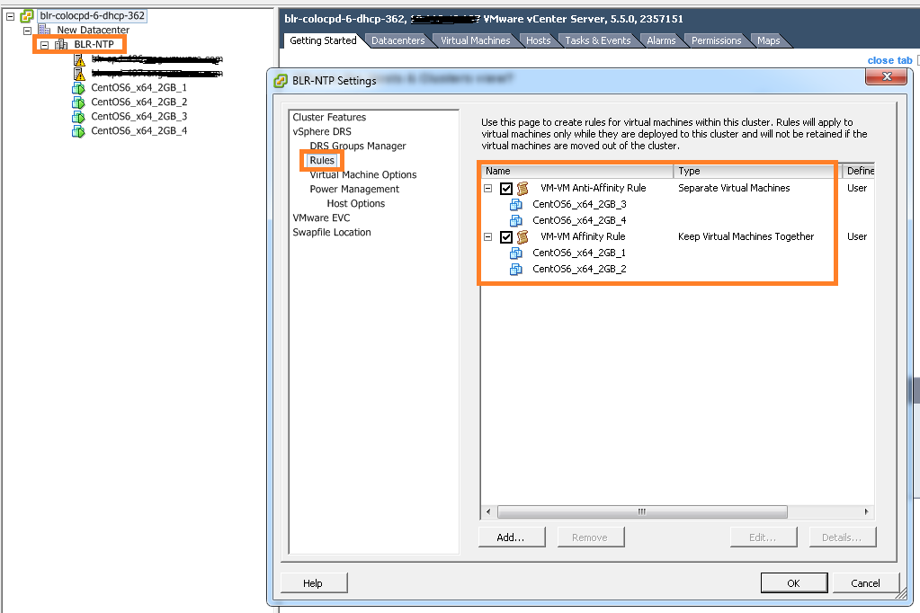
Below is the VI client view of created VM-VM DRS rules using above code.
VM-VM Rules

If you have still not setup your VI JAVA Eclipse environment:Getting started tutorial
Important tutorials to start with: Part I & Part II

DRS rules PART I: How to create VM-Host affinity rules using vSphere API

On high level there are 2 types of DRS rules, one is VM-VM affinity rules and other is VM-Host affinity rules. Today in Part I, I will brief on what are the VM-Host affinity rules DRS has & what are the use cases where VM-Host rules can be used. However more focus would be on how to create VM-Host rules on ESXi cluster using vSphere API. In general, VM-Host rules will allow us to run particular group of VMs on specific group of ESXi hosts or away from specific group of ESXi hosts.

Update: Part II is published as well on creation of VM-VM affinity rules using vSphere API

What are the DRS VM-Host rules we can create on ESXi host cluster.
1. VM-Host must affinity rule : It is mandatory rule where specific group of VMs must run on specific group of hosts.
2. VM-Host must anti-affinity rule : It is mandatory rule where specific group of VMs must not run on specific group of hosts.
3. VM-Host should affinity rule : It is soft rule where specific group of VMs should run on specific group of hosts. DRS or user can violate this rule whenever required. But DRS will make best effort to correct the violation in the next DRS invocation.
4. VM-Host should anti-affinity rule : It is soft rule where specific group of VMs should not run on specific group of hosts. DRS or user can violate this rule whenever required. But DRS will make best effort to correct the violation in the next DRS invocation.

What are the use cases where we can use these rules
1. There are some products their licenses are based on ESXi host CPUs, it is mean that you need to apply licenses on these ESXi host to run the VMs. Classic example is Oracle licensing for databases. In this case, we can configure VM-Host must affinity rule so that oracle DB VMs will only run on set of hosts with oracle license.
2. VM host anti-affinity rule can be used to increase the availability of the VM. i.e. Running some critical VMs on set of hosts with different power supplies than rest of the host in the cluster so that even when there is power failure, some critical VMs can be still running on set of host with different power supplies.
I strongly suggest you to read my blog post is vSphere HA aware of DRS rules in order to understand impact of the DRS rules on vSphere HA.

Now it is time to look into creating these rules using vSphere APIs. Before jumping on developing code, It would be great if you get familiar with ClusterConfigSpecEx data object required for creating VM-Host rules. Specifically focus on data object properties high-lighted in below screenshot.
RuleSpec_GroupSpec

Below code is for creating VM-Host must affinity rule, I will explain how to leverage this code to create other 3 rules. It is really very simple.
[java]
package com.vmware.vijava;
import java.net.URL;
import com.vmware.vim25.ArrayUpdateOperation;
import com.vmware.vim25.ClusterConfigSpecEx;
import com.vmware.vim25.ClusterGroupInfo;
import com.vmware.vim25.ClusterGroupSpec;
import com.vmware.vim25.ClusterHostGroup;
import com.vmware.vim25.ClusterRuleSpec;
import com.vmware.vim25.ClusterVmGroup;
import com.vmware.vim25.ClusterVmHostRuleInfo;
import com.vmware.vim25.ManagedObjectReference;
import com.vmware.vim25.mo.ClusterComputeResource;
import com.vmware.vim25.mo.Folder;
import com.vmware.vim25.mo.HostSystem;
import com.vmware.vim25.mo.InventoryNavigator;
import com.vmware.vim25.mo.ServiceInstance;
import com.vmware.vim25.mo.VirtualMachine;
import com.vmware.vim25.mo.util.MorUtil;

public class VMHOSTrule {

public static void main(String[] args) throws Exception {
if (args.length != 3) {
System.out.println("Usage: java SearchDatastore [url] "
+ "[username] [password]");
return;
}

ServiceInstance si = new ServiceInstance(new URL(args[0]), args[1],
args[2], true);
/*
* you need to pass 3 parameters 1. https://x.y.z.r/sdk 2. username 3.
* password. Plz connect to vCenter Server
*/
String vmGroupName = "vmGroup_1";
String hostGroupName = "HostGroup_1";
Folder rootFolder = si.getRootFolder();

ClusterComputeResource clu = null;

clu = (ClusterComputeResource) new InventoryNavigator(rootFolder)
.searchManagedEntity("ClusterComputeResource", "India_Cluster");
ManagedObjectReference ClusterMor = clu.getMOR();

HostSystem host1 = (HostSystem) new InventoryNavigator(rootFolder)
.searchManagedEntity("HostSystem", "10.10.1.1");
HostSystem host2 = (HostSystem) new InventoryNavigator(rootFolder)
.searchManagedEntity("HostSystem", "10.10.1.2");
ManagedObjectReference hostMor1 = host1.getMOR();
ManagedObjectReference hostMor2 = host2.getMOR();
VirtualMachine vm1 = (VirtualMachine) new InventoryNavigator(rootFolder)
.searchManagedEntity("VirtualMachine", "CentOS6_x64_2GB_1");
VirtualMachine vm2 = (VirtualMachine) new InventoryNavigator(rootFolder)
.searchManagedEntity("VirtualMachine", "CentOS6_x64_2GB_2");
ManagedObjectReference vmMor1 = vm1.getMOR();
ManagedObjectReference vmMor2 = vm2.getMOR();
ClusterComputeResource ccr = (ClusterComputeResource) MorUtil
.createExactManagedEntity(si.getServerConnection(), ClusterMor);
ManagedObjectReference[] vmMors = new ManagedObjectReference[] {
vmMor1, vmMor2 };
ManagedObjectReference[] hostMors = new ManagedObjectReference[] {
hostMor1, hostMor2 };

ClusterGroupInfo vmGroup = new ClusterVmGroup();
((ClusterVmGroup) vmGroup).setVm(vmMors);
vmGroup.setUserCreated(true);
vmGroup.setName(vmGroupName);

ClusterGroupInfo hostGroup = new ClusterHostGroup();
((ClusterHostGroup) hostGroup).setHost(hostMors);
hostGroup.setUserCreated(true);
hostGroup.setName(hostGroupName);

ClusterVmHostRuleInfo vmHostAffRule = new ClusterVmHostRuleInfo();
vmHostAffRule.setEnabled(new Boolean(true));
vmHostAffRule.setName("VMHOSTAffinityRule");
vmHostAffRule.setAffineHostGroupName("HostGrp_1");
vmHostAffRule.setVmGroupName("VMGrp_1");
vmHostAffRule.setMandatory(true);
ClusterGroupSpec groupSpec[] = new ClusterGroupSpec[2];
groupSpec[0] = new ClusterGroupSpec();
groupSpec[0].setInfo(vmGroup);
groupSpec[0].setOperation(ArrayUpdateOperation.add);
groupSpec[0].setRemoveKey(null);
groupSpec[1] = new ClusterGroupSpec();
groupSpec[1].setInfo(hostGroup);
groupSpec[1].setOperation(ArrayUpdateOperation.add);
groupSpec[1].setRemoveKey(null);
/* RulesSpec for the rule populated here */
ClusterRuleSpec ruleSpec[] = new ClusterRuleSpec[1];

ruleSpec[0] = new ClusterRuleSpec();
ruleSpec[0].setInfo(vmHostAffRule);
ruleSpec[0].setOperation(ArrayUpdateOperation.add);
ruleSpec[0].setRemoveKey(null);
ClusterConfigSpecEx ccs = new ClusterConfigSpecEx();
ccs.setRulesSpec(ruleSpec);
ccs.setGroupSpec(groupSpec);

ccr.reconfigureComputeResource_Task(ccs, true);
System.out.println("VM Host Rule created successfully");

}

}

[/java]
Line 22-29: Refer my this blog post on ServiceInstance data object to understand these lines.
Line 41-54: Refer my this blog post on Inventory Navigator to understand these lines.
Line 64-72: We are populating VMGroup i.e. Set of VMs of those will be part of rule. & HostGroup i.e. set of hosts those will be part of rule. These groups will be pinned with GroupSpec in line 80-88.
Line 74-78: Creation of ClusterVmHostRuleInfo data object which helps to identify which host group and VM Group is associated with this rule as there can be several other host and VM groups associated with other rules already exists or planned to configure. Note that line 77 is responsible in deciding whether rule is affinity or anti affinity.
Line 80-88: Here we are populating GroupSpec required for creating VM & Host group on cluster based on the line 64-72.
Line 90-95: Here we are populating RuleSpec based on line 74-78.
Line 96-98: Populating ClusterConfigSpecEx data object with RuleSpec and GroupSpec which will be passed to reconfigureComputeResource_Task method which actually re-configures cluster with created VM-Host must affinity rule.

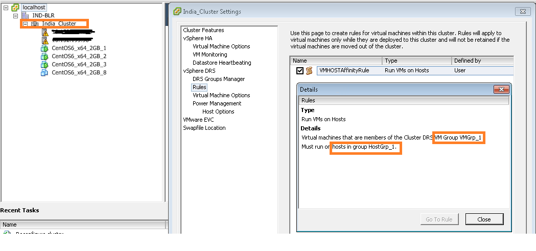
Here is the created VM-Host rule view from vSphere Client.
VM Host Rule

Noteworthy points:
1. For the sake of simplicity we have hard-coded some IPs, cluster, host & VMs names. Please do make changes if you are using this in production environment.
2. In order to create anti-affinity rule, you will just need to replace line 77 to vmHostAffRule.setAntiAffineHostGroupName(“HostGrp_1”); is it not too simple?.
3.In order to make this rule soft, just replace line 79 to vmHostAffRule.setMandatory(false); Note that default rule created is soft rule(i.e. If we do not set the property).

I hope you enjoyed this post, please take a look at Part II on VM-VM affinity rules creation.

Learn more on VM-Host rules here.
If you have still not setup your Eclipse environment:Getting started tutorial